Week Four
- Jan 27, 2025
- 4 min read
Updated: Feb 9, 2025
Posts arranged newest to oldest.
Project 2 Directions: https://www.gracieszymanski.com/post/technical-direction-for-compositing-project-2-directions
2/2/25
Today, I attempted to fix my 3D camera tracker again. I started from scratch again and used more trackers this time in hopes it would be more accurate. I used 500 trackers and imported it to Maya yet again my issue was not solved.

I am feeling a bit behind now because I focused a lot on tracking this weekend instead of the materials of my bunny. I know I will catch up and the 3D camera track is only extra credit, but I really want to get it working. I am also feeling a bit behind as I missed a class last week and am struggling to catch that up but I am confident I will pull it together before the due date.
That being said, I did still fully set up my file for my Stanford bunny with my chosen plate and began creating the render layers for my project. For this project, we are combining render layers with different materials and comping them together in Nuke in order to get that crystal look.
First things first, before I began setting up my materials I did my chrome and white sphere tests to set up my key light and HDRI. I moved onto setting up my beauty layer, shadow layer, and occlusion layer as done in the previous project. When I got to my shadow layer, I realized that my bunny shadow would be casting onto the crystal towers in my plate, therefore I went ahead and quickly modeled and placed these towers in my scene:

I'll have to go back in an prefect the models and bevel some edges but this is how my shadow plate came out with these objects:

After this I went to start setting up my material layers:
Glass
Subsurface
Fresnal
Specular


I still need to add in my volume render and more properly organize and define my nuke tree, but with some of these layers comped together, here is my first initial comp of the bunny in my scene:

Another thing I will definitely need to do is figure out a way to make it look like the bunny is actually sitting on that fuzzy surface, whether it be through a roto or some other way.
2/1/25
Today I wanted to focus on 3D tracking my plate. Part of the assignment was taking a pan or video of our plate and then using a 3D tracker in nuke to create a camera that could be imported into Maya. After feedback from the professor I chose to go with option 2 for my plate (as discussed in the previous entry) but may end up going back and adding my crystal bunny to both plates as it would not be much extra work. As I began to start to track the mp4 camera move file I shot, I noticed how different the video looked from the still images I had:

The first thing I did to my plate was add a color correct and hue correct to adjust the tones and saturation of the video. Here is the corrected still and moving plates.

In NukeX I used the 3D camera tracker node to track my footage. I had an error margin of only .46. I also used points to declare a ground plane to make the 3D space more accurate.


I then exported this camera using the write geo node and opened it up in my Maya. I noticed how wildly different the camera I used from Nuke was from the original camera I tried to match. Upon putting a cube and a bunny onto my grid in my file, I realized something was very off.


Upon seeing this issue, I went back into Nuke and retracked the camera multiple times. I played around with a lot of settings in Nuke as well. I imported into Maya multiple times and spent about 4 hours troubleshooting. I plan to retry in the morning. In the meantime, since the 3D tracker part of the assignment was technically optional and extra credit, I decided to do a 2D track on my previous project to meet the requirements of the project, in case I cannot figure out my 3D tracker issue.
For this track, I 2D tracked another plate provided to me by the professor and then applied that camera movement to my project:
1/28/25
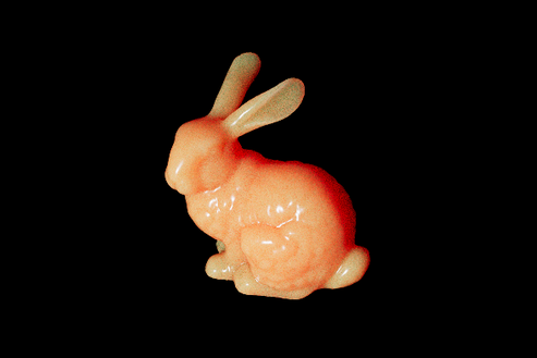
For project two, I will be using the Stanford Bunny as my object that I will turn into a crystal bunny. This model is very commonly used in testing computer graphics due to its 69,451 triangles and its curves and small details that it make it the perfect test dummy.

As previously mentioned in my last blog, I was able to shoot some plates for project two, two weekends ago. This past weekend, I also shot more possible plates for it. To help me decide, I am going to quickly camera match both options and put my model in so that I can see which option will look better.
Clean plates taken by me:
Option 1 and Option 2


Once again, to match the camera I will be using the 35 mm focal length of the camera I physically used and I will be creating a camera in Maya and matching a cube up with the photographed cube as close as possible to get the closest possible camera.
Camera information from both:

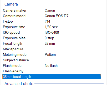


To find the 35 mm focal length, like I have done before, you use the focal length times to crop factor:
Option 1: crop factor of 1.6 x 32 mm focal length = 51.2
Option 2: crop factor of 1.6 x 36 mm focal length = 57.6
Camera matches:


Stanford model:


